
Working Theory Of A Half Wave Rectifier Circuit And Its Waveform

Half Wave Rectifier
When a AC waveform is applied and when half of the AC cycles gets rectified, it is called as half wave rectifier. The output voltage of the half wave rectifier is not pure DC as the AC components are present in this voltage. This AC component is called as ripple voltage. In half wave rectification, the rectifier only conducts during the positive half cycles of the alternating current (AC) supply. During negative half cycles, no current is conducted, and as a result, there is no voltage across the load.
Circuit Diagram
Circuit Details
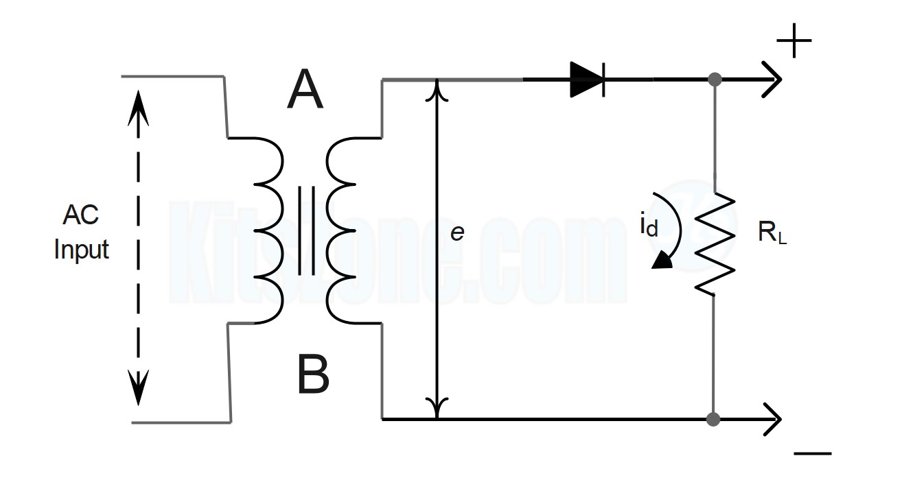
In the circuit presented above, a single diode functions as a half-wave rectifier. The to-be-rectified AC supply is connected in series with the PN junction diode and a load resistance RL. In this experiment, the AC supply is obtained through a transformer. The use of transformer offers two benefits.
First, it allows us to increase or decrease the AC voltage depending on the circumstances using a step up or step down transformer.
The transformer also isolates the rectifier circuit from the power line, reducing the risk of electric shock.
Circuit Working
A is positive with respect to B when an AC supply is applied to the input circuit during one half of the cycle. This makes the diode's P terminal positive with respect to its N terminal. Consequently, the diode is forward biased, and current travels through the load RL in the direction depicted in the circuit above. During the subsequent half-cycle, the point A is negative relative to point B. Consequently, the diode is reverse biased and does not conduct (except for a very small reverse current which is negligible), so no current flows through the load RL.
The diode conducts during the positive half cycle and does not conduct during the negative half cycle. Thus, when an AC signal is applied to the input of the rectifier, only one-directional current flows through RL. The output across RL will therefore be a DC. The wave forms of the input and output are shown below. As the output comprises only the positive half of the input wave, this rectifier is referred to as a half-wave rectifier.
Input And Output Waveform


Mathematical Analysis
Let e = E0 + sin wt be the input voltage to the rectifier, where E0 be the peak input voltage. When the diode is conducting, let id be the current flowing through the circuit and let the voltage drop across the diode be ed.
Assuming the ohmic resistance of the secondary of the transformer as negligible and applying Kirchhoff's voltage law to this circuit we have,
$$\begin{array}{*{20}{l}}{e = {e_d} + {i_d}{R_L}}\\{{\rm{\;}} = {i_d}{R_f} + {i_d}{R_L}}\end{array}$$

If the resistance of the diode is negligible compared to RL, then


DC Value Of Current (Idc)
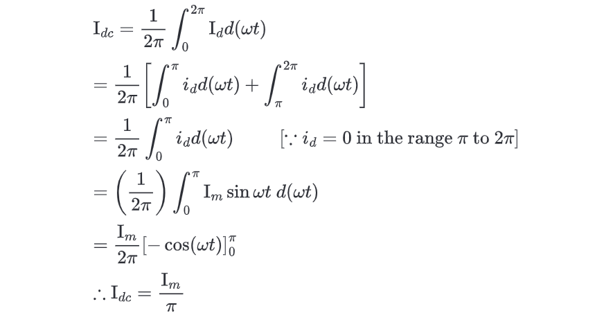
From the second graph, it can be noticed that the output current is not steady but contains fluctuations despite of being a DC current. The average value of this fluctuating DC current can be calculated as follows:
RMS Value Of Current (Irms)

Efficiency (η)


Ripple Factor(r)
At the output of half wave rectifier, periodically varying components are still present even though we have achieved a unidirectional current. Filters are used in the rectifier to reduce the varying components. A measure of the varying component is given by the ripple factor as follows:

Instantaneous value of ripple current I' = id – Idc

Using equations below


Ripple factor is given by

The above calculation shows that the RMS value of the ripple exceeds that of the DC potential of the output. This shows that the half wave rectifier without a filter is relatively a poor device for converting AC into DC.
Peak Inverse Voltage
It is defined as the maximum voltage applied across the diode when the diode is reverse biased. In the case of half wave rectifier, the maximum voltage across the diode when it is not conducting is equal to E0, the peak input voltage.


COMMENTS