


Fully Automatic Water Level Controller Circuit With Motor Dry Run Protection Without Using A Microcontroller

Automatic water level controllers regulate the water supply for a given reservoir/tank to maintain a minimum water level. This water level controller circuit uses a float switch to control the water level of the storage tank. It is an automatic system, so it will start to fill up when the height of the water goes below a certain point. If it reaches full capacity, the float switch will automatically turn off. This protects against overfilling and spilling of water. The water level controller manages the level of water in a tank. It automatically detects the tank's water level and turns the pump on or off to maintain it at the desired level. The float switch helps detect different levels of water by using a magnetic switch module that floats on top of the water.
FEATURES OF THIS CIRCUIT: [Buy Kit ##cart-shopping##]
- Low-cost circuit made out of readily available components.
- Low power consumption.
- Turns on the pump when the level of water goes below bottom level.
- Turns off the motor when the water reaches the top level.
- Turns off the motor when there is no water in the sump or well.
- When power fails and resumes later if the water level is below the bottom, it will automatically turn on the pump.
- Motor dry run protection.
- Compact size
- Can be used for motors up to 3HP power.
- Fully automatic control. Manual on and off switch option.
- Semi On and Off option available
- Top, Bottom, Flow, Power and Motor On indicator LED
Parts Required: [Buy Kit ##cart-shopping##]
Working Of the Circuit: [Buy Kit ##cart-shopping##]
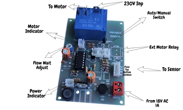
The AC voltage from the stepdown transformer (12V, 15V or 18V can be used) is fed to the bridge rectifier (DB1) in order to get a DC volt. The output DC is filtered by capacitor C1. It is fed to the input of the regulator U1. The negative of the output volt is connected to the L1 and C3 to avoid line disturbances. The DB1 shown in the image is optional. The heart of the circuit is the dual timer IC U2. The trigger and threshold pins 8 and 12 detect the low and high levels of water in the tank. The reset pin 4 and output pin 9 are connected together. Transistor Q1 is used to detect the water flow. The collector of the transistor Q1 is connected to the trigger pin 6 of U2 through a diode D4. The output pin 5 of U2 is fed to the base of the NPN transistor Q1 through a resistor R13. The push button switch ON is a normally closed type used here to turn on the pump. Once activated, the pump will be turned off by pressing OFF switch which is normally open type or when the water level touches the top float or water flow stops in the middle.
Once the unit is powered on, LEDs L2 and L6 will be turned On and the relay gets activated. Once the relay is activated, it will wait for a few seconds and checks whether the water is flowing into the tank or not. The wait time can be adjusted by the preset R3. If there is no flow of water, it will automatically turn off the pump. In this scenario, we have to turn off the device and turn it ON once the issue is sorted out. If the water continues to flow, the relay will remain activated until it reaches the top float or the OFF-push button is pressed.
We can turn on and turn off the pump using the ON and OFF push button switches provided the water level is between the bottom and top level. Manual/Auto switch option is available in this circuit. It is achieved by directly connecting to the relay bypassing the circuit. We can also connect a Manual/Auto switch externally bypassing the relay. This circuit is 100% safe and corrosion proof as it uses magnetic float switches.As the components are readily available in the market, we can easily build this circuit.
Please ensure that you are using good quality float switches. With a slight modification in the external connection, this circuit can be used as a semi - automatic water level controller too!

Water Level Controller Readymade Kit

Water Level Controller Connection Details:
Semi-automatic Controller Connection Diagram:

Sensor Connection For Municipal or Governement Water Supply

Can use any of the following Float Switches:
Horizontal Magnetic Float Switch:

Vertical Magnetic Float Switch:

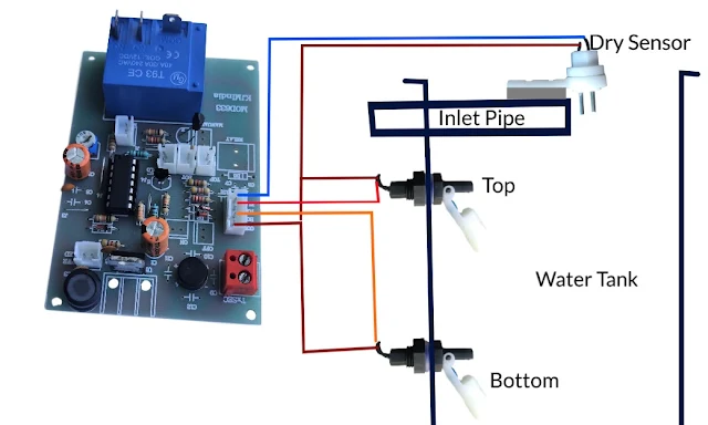
Cable Float 5A, 250V: Top and Bottom sensors are shorted. One terminal of float switch is connected to the shorted terminal and black wire of the float is connected to the common. (If you have any doubt, please comment below your queries)

Dry Run Sensor Outer View:

Dry Run Sensor Inner View

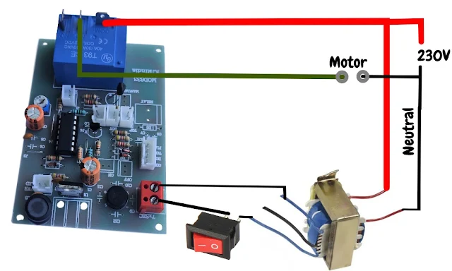
Water Level Controller Power And Relay Connection Diagram:
Water Level Controller Sensor Connection Diagram:


pls give me the pcb layout
ReplyDeletehttps://ekitszone.gumroad.com/l/mod633gerber
DeletePcb layout diagram pLz sir
ReplyDeletehttps://ekitszone.gumroad.com/l/mod633gerber
DeleteCirtuit does not seems to be working, 4.7k resistor is too big to glow an led
ReplyDeleteCan you please share your prototype? If it is not working for you, please try with 3.3k
DeleteYou said that if no flow unit will turn off ,for how long it will keep off? Is there any time elapse? Because of I’m not near by the unit it will start switching on/off? Please explain
ReplyDeleteIt will be turned off permanently until we reset the device by turning off and turning on the power switch of the device.
DeleteCan you send diagram to connect vertical magnetic float switch
ReplyDeleteThe connection diagram to connect vertical float is similar to the horizontal float. We just have to replace the horizontal float with a vertical float. Vertical floats can be suspended inside the water tank as per our required levels.
DeleteThis not 556 ic ...fake circuit is ok but ic no
ReplyDeleteI have uploaded an enlarged image of the circuit board. Please zoom in and check the value of the ic. https://drive.google.com/file/d/1AEvzXFQMC7iSGFeOPruqO18tGMbZTxur/view
DeleteSir can i use carbon sensor???
DeleteYes. But it is advisable to use float switches to avoid reactions in the water.
DeleteWhich kind of reaction sir?
DeleteElectrolysis
DeleteSir i use this circuit since 3-4 day. But now the controler automatically on when water bellow top level sensor and automatically of when water touch top level sensor so what is the problem .. Pls guide me
DeletePlease share more details like image of the circuit board, float switch used, transformer specification to zonekits @ gmail.com with your whatsapp number.
DeleteSir i made this circuit in "circuit wizard" software and tried to run it, but it did not run then i moved pin 10 wire and 33k resistor from ground to positive the it starts working, whats wrong with your circuit diagram, pls check it. I want to make it on zero pcb, thanks
ReplyDeleteI haven't used the tool "circuit wizard" so, It is hard for me to comment on this. There is nothing wrong with the circuit. It has been working perfectly for many years. If you are living in India, you can buy the readymade board or else try assembling it on zero pcb.
DeleteSorry Sir its not possible for me to buy this becaise i lives on abroad, can you share the picture of pcb of solder side also?
Deletehttps://ekitszone.gumroad.com/l/mod633gerber
DeleteI had purchased this circuit from you and it's working fine with mono block pump. But do you have any controller for Submersible water pumps where starter panel is used with start Stop button...
ReplyDeleteI am glad to hear that it is working fine. Please contact us through the following URL: https://kjmindia.in/contact-us
DeleteCan u pls add a buzzer sounds when flow not detected and pump stop condtion
ReplyDeleteThis feature will be added in the new version.
DeleteSir,, can u make a circuit with under and over voltage protection included in this automatic water level control. As there is voltage drop after 7:30 to 10 pm in my area and the controller start the motor when water gets low during these time.
ReplyDeleteMay I know the type of power supply you are using for this circuit: Transformer or Smps?
Delete